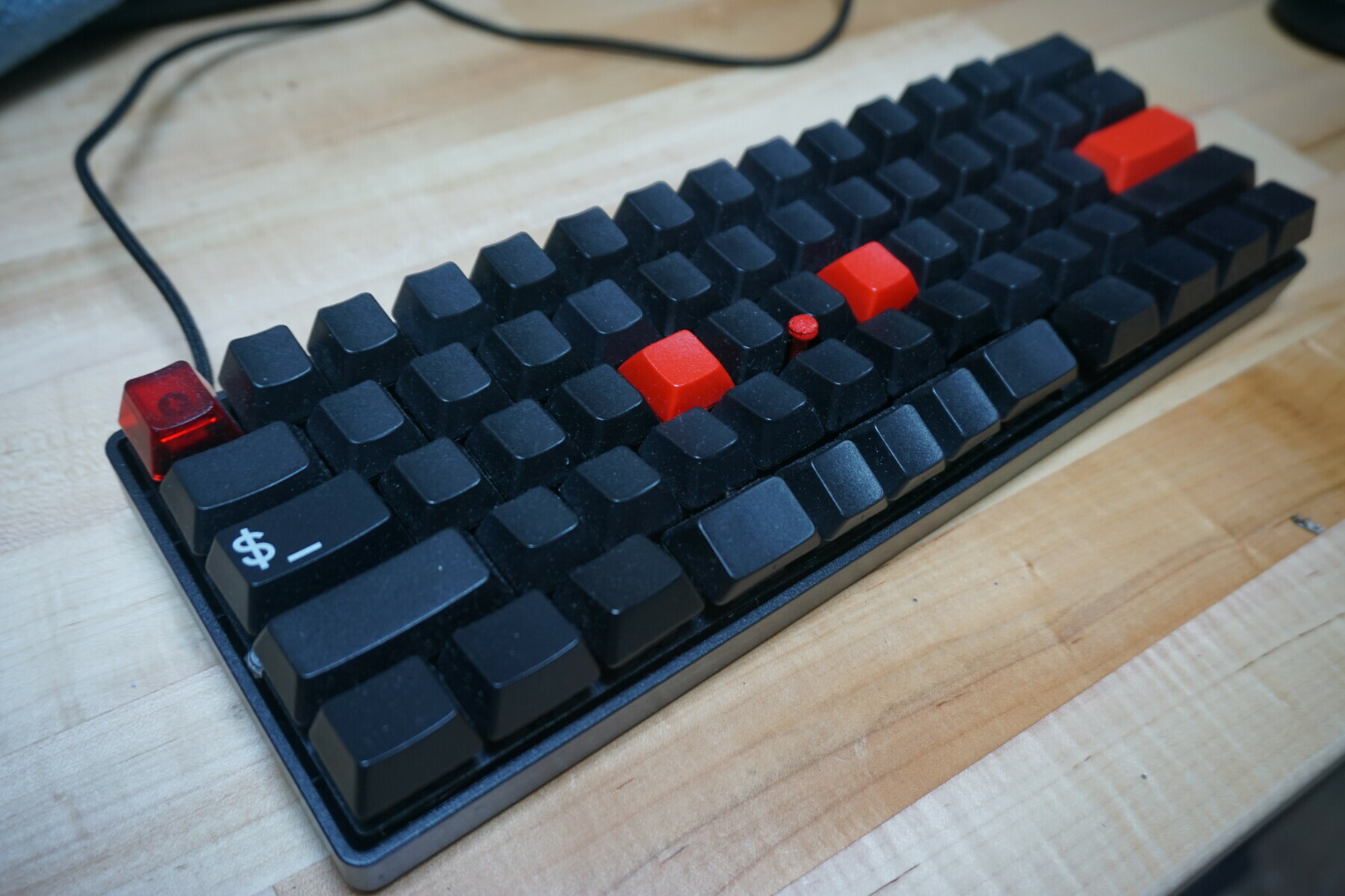
I’ve used a mechanical keyboard for many years now. I currently own a tenkeyless layout, even though as a programmer I almost never use the arrow cluster or function row, so I to try the much more compact 60% design. I also no longer care for the Cherry MX blue switches on my old board since they are quite loud, so I went with MX clears instead in this new design.
I have also owned many ThinkPads to use in conjunction to my desktop’s mechanical board. While ThinkPads have, in my opinion, the best laptop keyboards, they are still nothing compared to a good mechanical keyboard. While I could just use a regular mechanical keyboard with my laptop when needed, all mechanical keyboard’s I could find are missing an important part of the ThinkPad’s keyboard, the trackpoint.
It because of these unique requirements that I decided to try and build my own keyboard. I’ve done plenty of small electronic projects before and thought it would be fun to attempt this new one. It also allows me to configure everything about this keyboard the exact way I want it.
Since I need to include a trackpoint stem in the middle of the board I also choose to go with hand wiring a board instead of printing a custom PCB to solder the switches onto. Since I have much more soldering experience than PCB design I didn’t think this would be too much more work and allows much more flexibility. I sure you could somehow fit a trackpoint to a PCB it would require much more work than I’m willing to give.
After doing some research on what others have done in the past to install trackpoints to their boards I found the best method is to simply savage an old trackpoint from an existing ThinkPad keyboard. This way a lot of the hard work and coding is already done for you, you just need to adapt it to work in your board with your microcontroller. I found an old IBM ThinkPad’s replacement keyboard for cheap on eBay, but there are many others you can find if you get creative and look hard enough.
parts
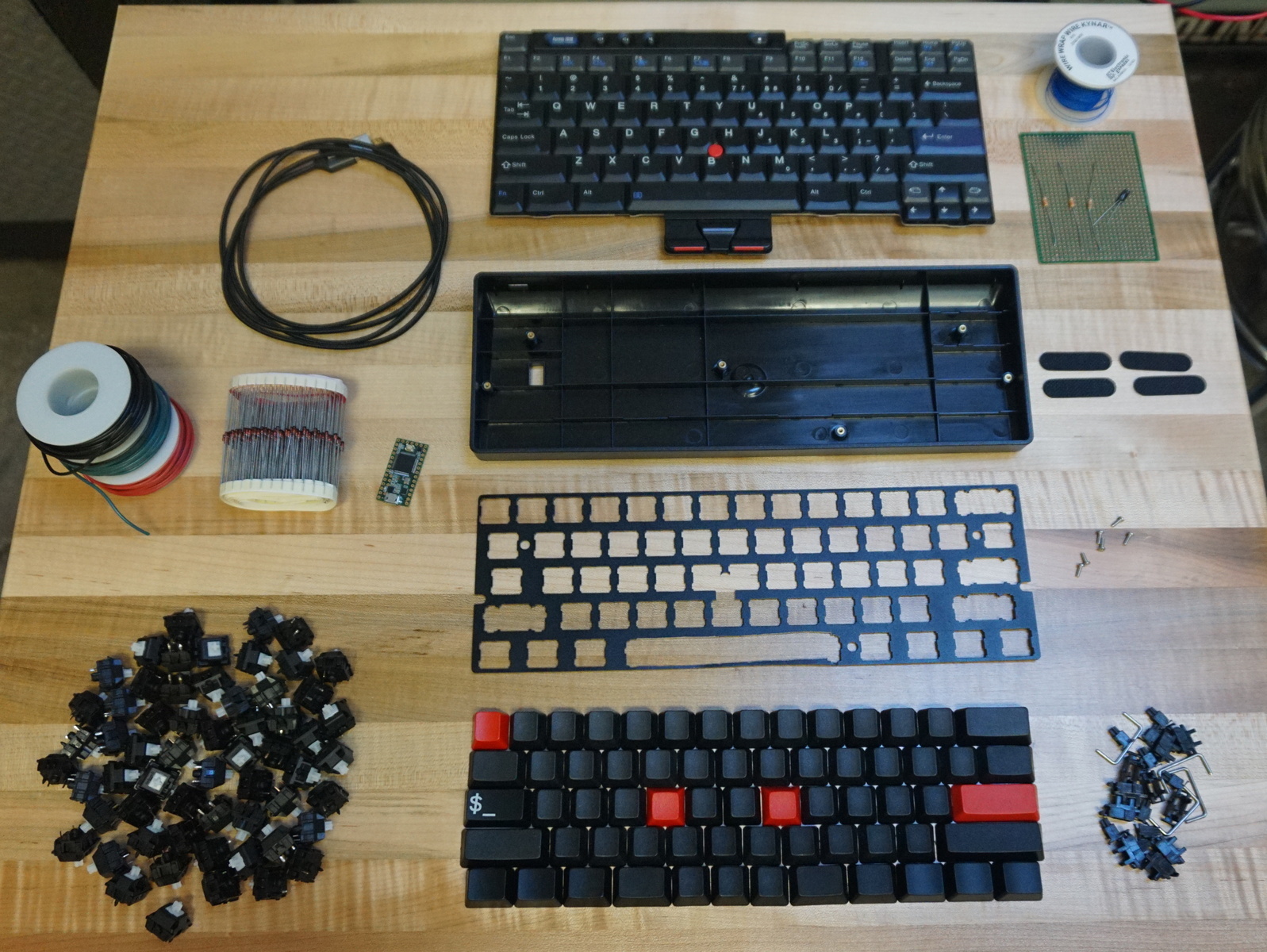
- 60% plastic case $15
- 60% aluminium plate $20
- Cherry MX Switches x61 ~$70
- Cherry MX Keycaps x61 ~$50
- MX Stabilizers $7.99
- Through hole diodes x61 $6
- 22 AWG Wire
- Teensy 2.0 or 3.2
- USB cable (micro or mini)
- Trackpoint module ~$15
- 1 kΩ Resistors x5
- 100 kΩ Resistor x1
- 4.7 kΩ Resistors x2
- 2.2 μF Capacitor x1
- 30 AWG wire $30
- Shrink wrap
- Perfboard
- Standoffs x5
- Trackpoint stem (be creative)
tools
- Hot glue gun
- Soldering iron
- Solder
- Wire strippers $21
- Needle nose pliers
- Philips screwdriver
- Multimeter (optional)
- Alligator clips (optional)
steps
1. cut aluminium plate
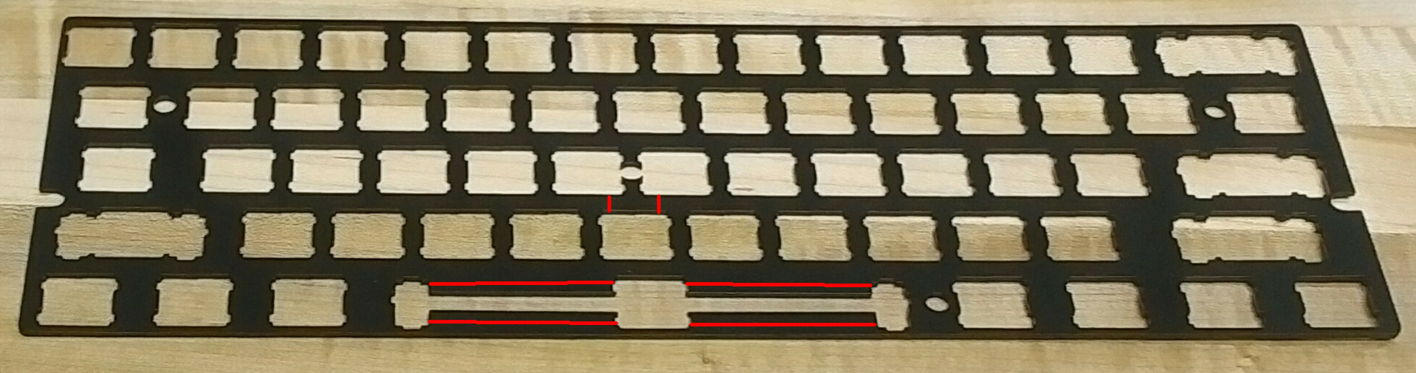
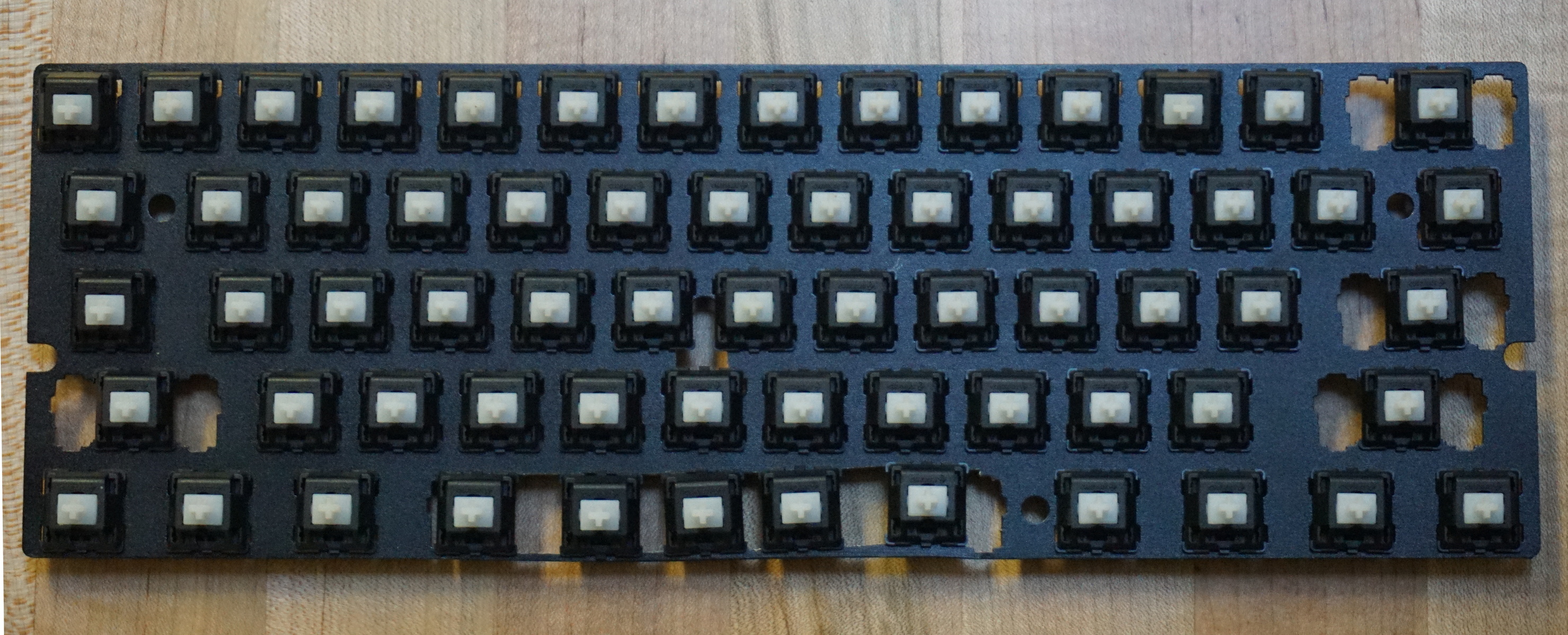
The first modification needed to support the trackpoint is to cut the metal plate used to hold the keycaps. This makes room for both the trackpoint’s stem and the 5 spacebar keys (2 spacebars surrounding the 3 mouse buttons). You can see where I made the cuts in read above. You have to be careful not to cut too much off, comprising the plates structure, while still making enough new room for the stem to move freely and the new keys to fit straight.
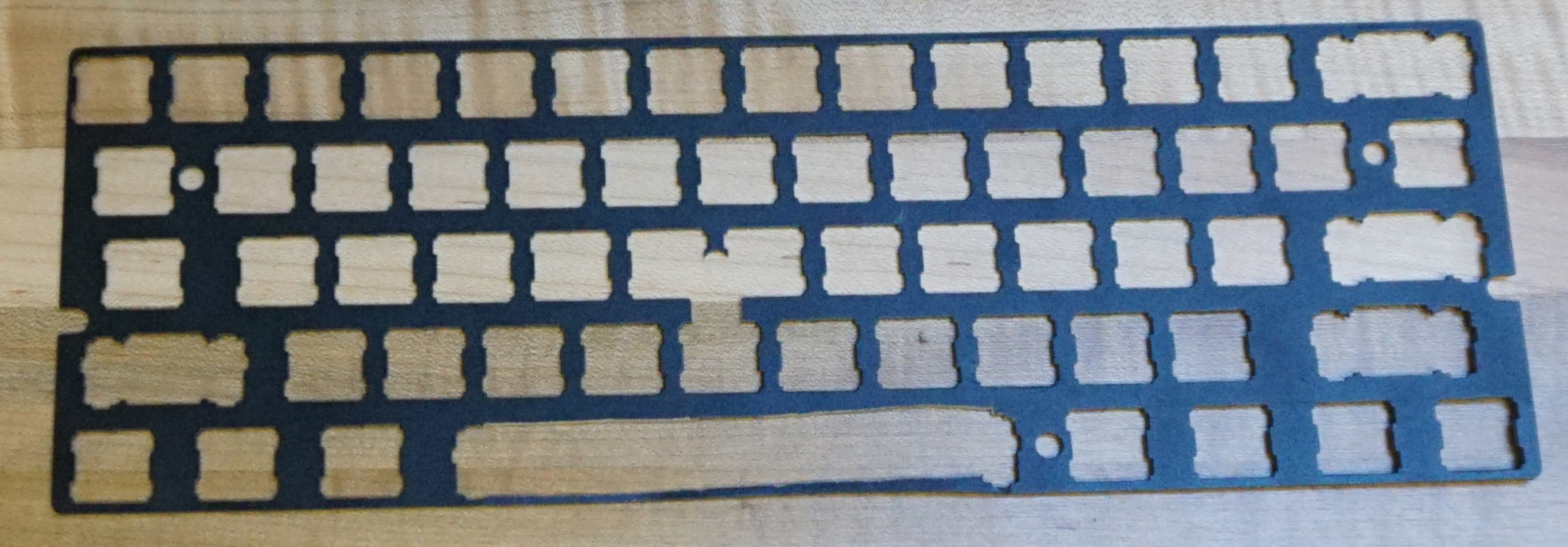
Shown above is the plate after the careful cuts. The right side of the spacebar didn’t turn out super straight so the far key ended up a little crooked, but can’t be noticed once the keycaps are placed.
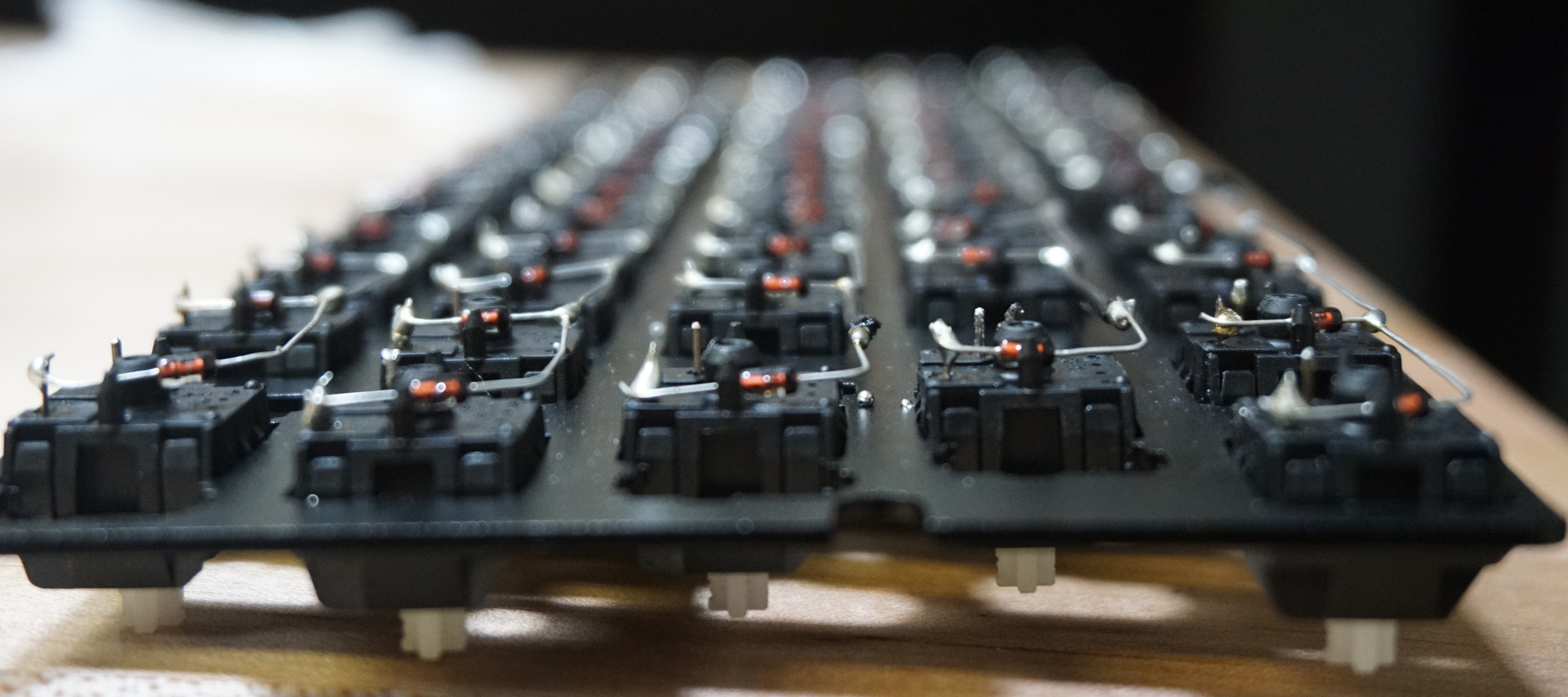
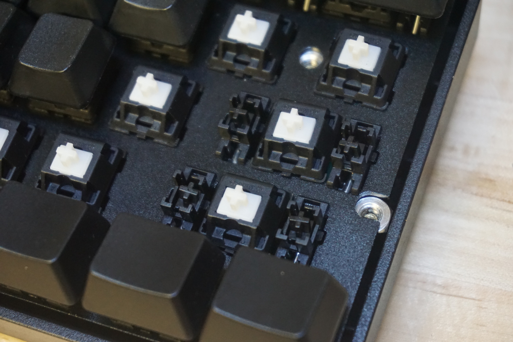
2. insert switches
Place your choice of mechanical switches into the cut plate, I went with Cherry MX clears. You might need to use some hot glue to hold the new spacebar keys in place depending on how straight and tightly you cut. Because we are hand wiring and not using a PCB to firmly attach the switches, hot glueing all the switches could be a good idea to make it more sturdy and easier to remove keycaps without pulling the switch out by mistake.
It might also be wise to add the key stabilizers at this step but I forgot this. You can add them later after everything is soldered but it is not as easy.
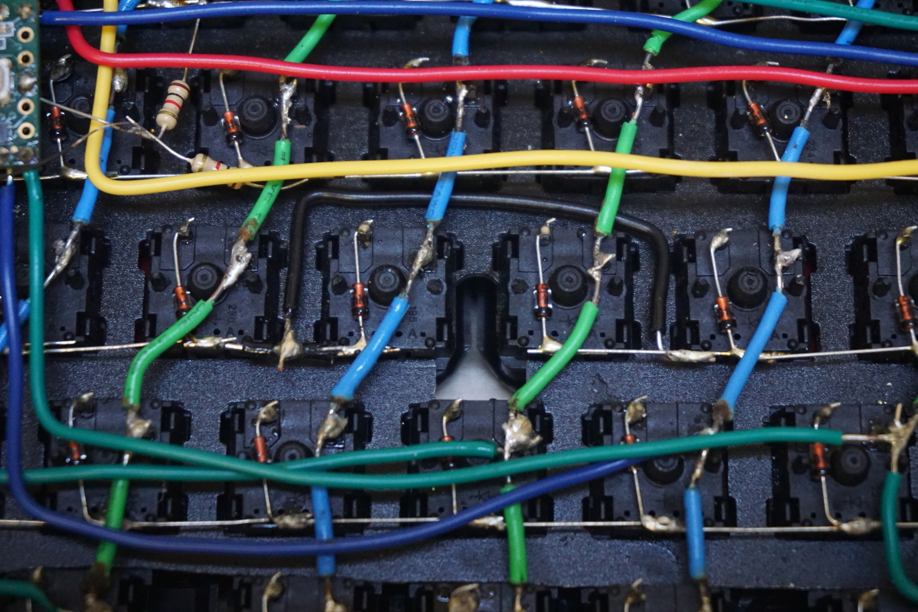
3. solder rows
a) prepare diodes
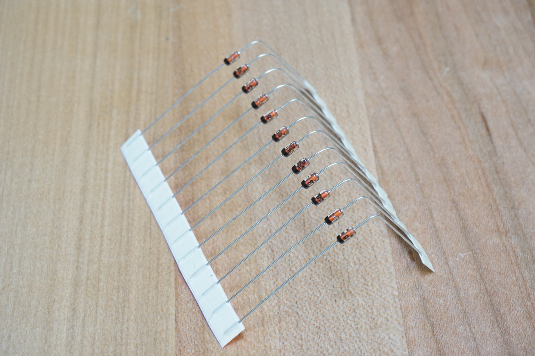
Cut off enough diodes from the bundle for the first row being soldered. With this strip you can bend them all 90° at once on the anode side (side without black or grey marking band), about a millimeter from the base. This joint is where they are soldered onto the switches pin. By doing this at once they will look more uniform in the finished product.It’s important which side you bend since the purpose of a diode is to act as a one way value, so if it’s facing the wrong way its not going to work.
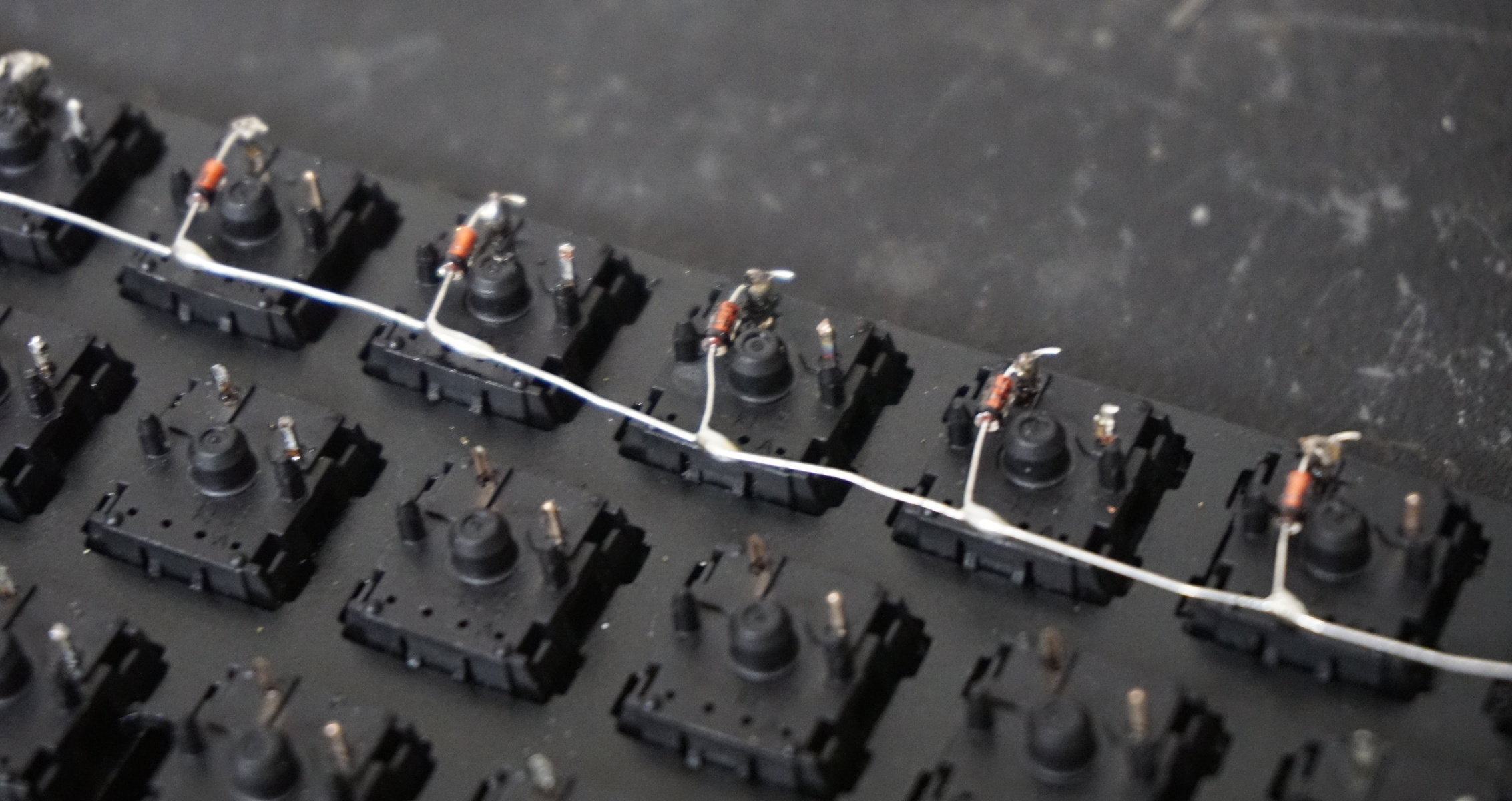
b) place solder globs
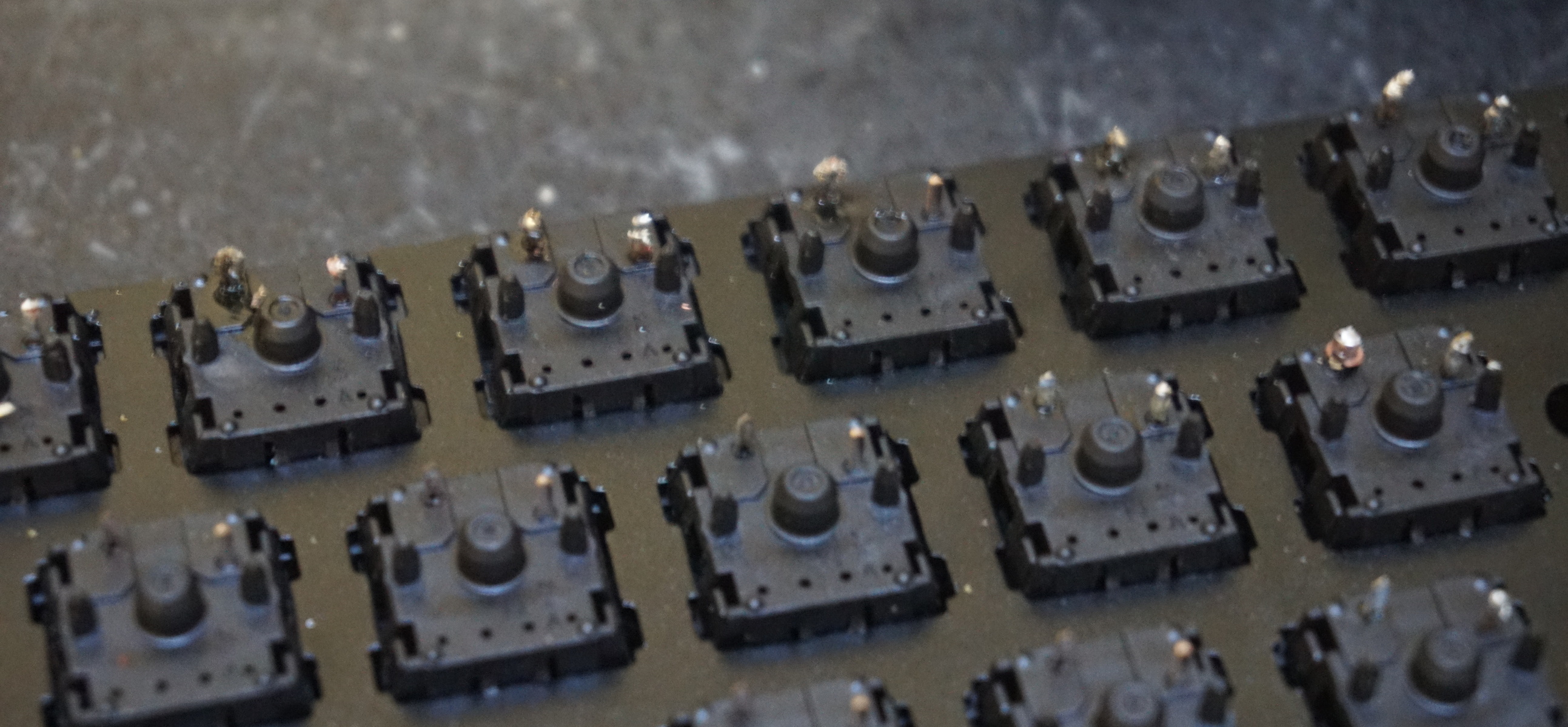
To prepare soldering the diodes, place a small glob of solder on the top left pin of each switch. I salvaged some of these switches from an old keyboard so the image above shows some additional left over solder.
c) attach diodes
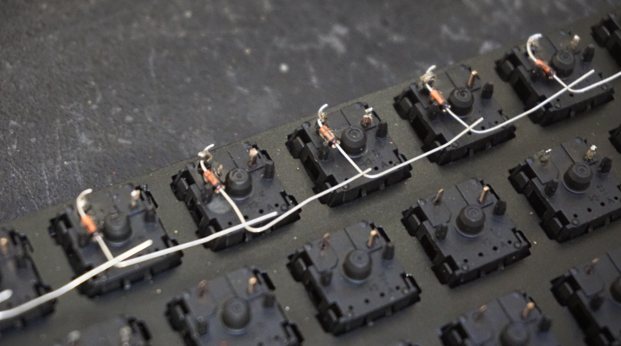
Use the pre placed glob to quickly solder the bent diodes down the row to all the switches. An additional bend is then made on the cathode side near the bottom of the switch so it can reach the next diode when they are linked in the next step. There should still be enough overlap so you don’t have to solder the end to the bend, around 2-3 mm worked for me. Before moving on you should use the wire cutters to trim to anode as to clear up some space.
d) link diodes
Lastly connect all the diodes in each row with a bit of solder. You might have to use some of that 22 AWG wire to extend the diodes if they don’t reach between the longer keys.
Black wire extenders:
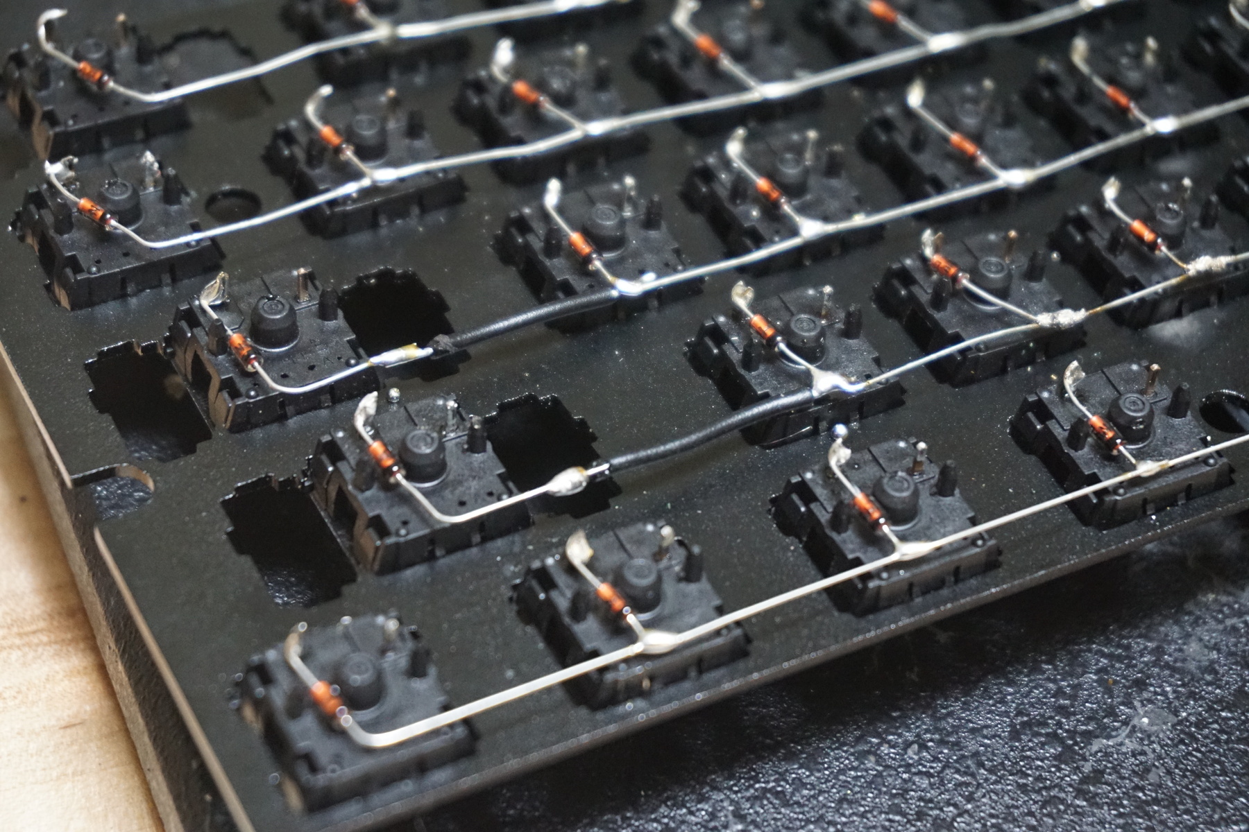
e) repeat
Repeat steps (a) through (d) for all the rows
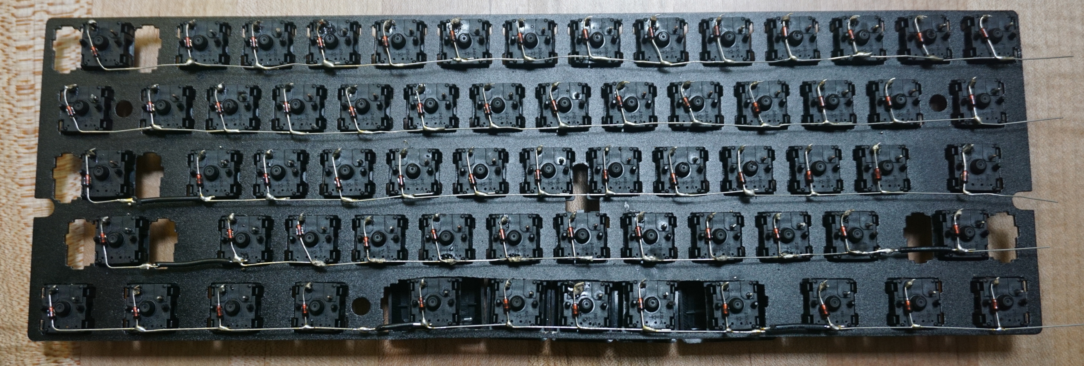
4. solder columns
Now that the rows are completed it’s time for the columns. The 22 gauge wire is used to connect the switch’s right pins downwards. The easiest way to do this is to cut a long wire to span the entire column with a bit left over. Simply use wire cutters or a blade to slice the insulation at each pin and push the insulation down before soldering. Leave enough wire at the end to attach the columns directly to the microcontroller in the next step to reduce soldering. In hindsight I could have left the extra wire at the top where the controller is located but either way works.
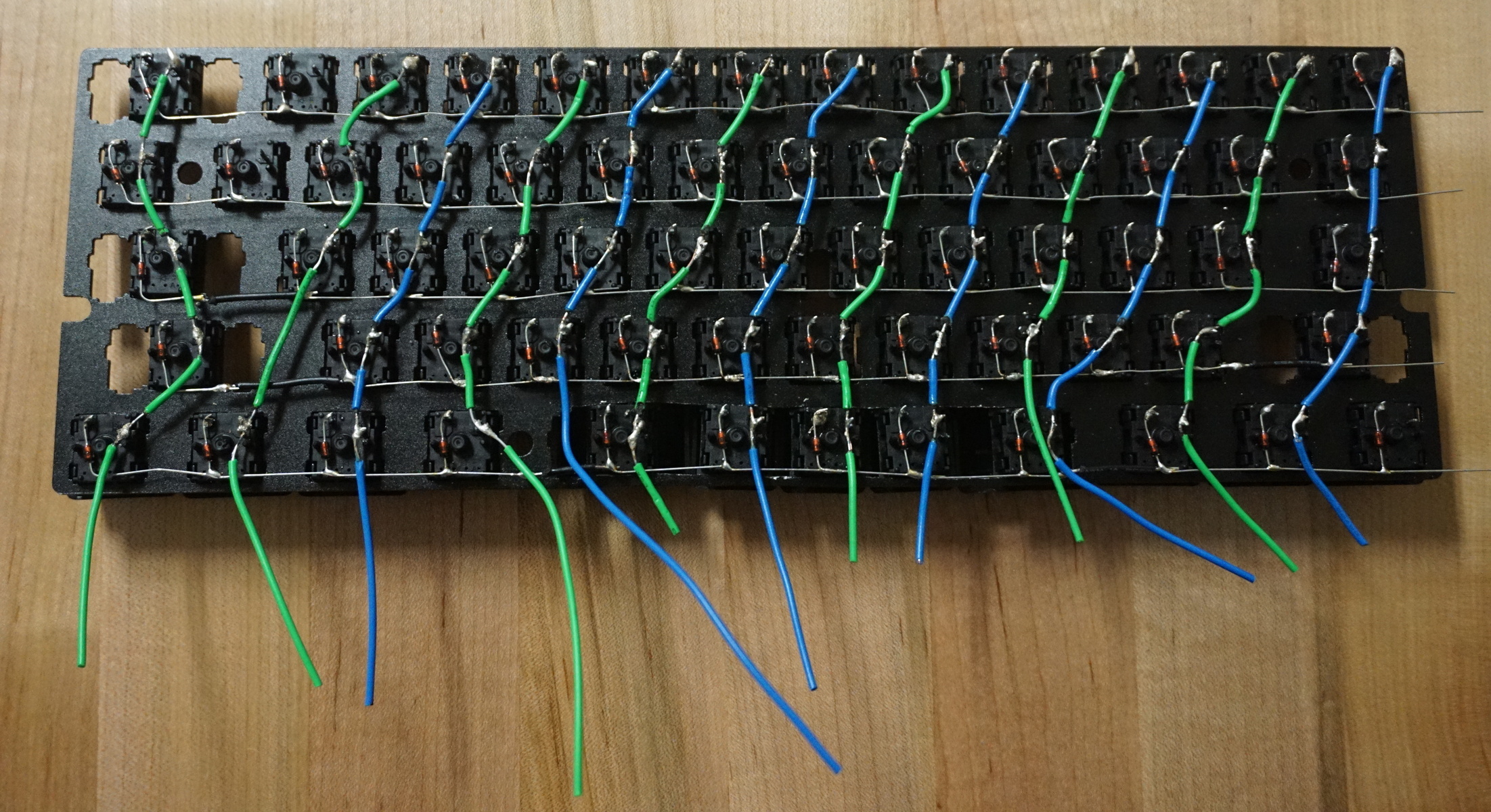
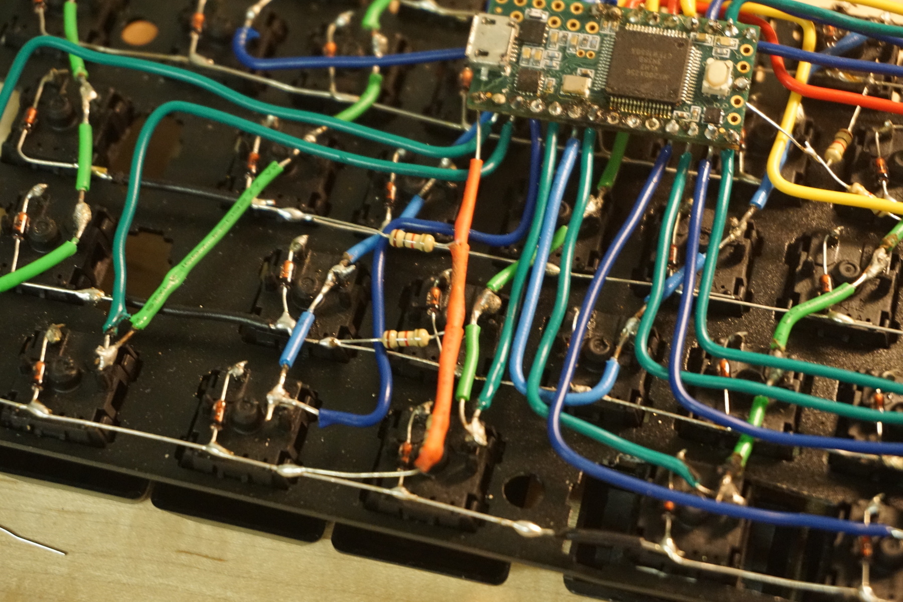
I used alternating colored wires to make connecting to the microcontroller more organized. If you are constructing a staggered layout keyboard like me you might not be able to connect every key to a complete column, I had two keys in the upper left and one in the bottom right as you can see. You can get creative with how you wire it, making a new short column like I did with the left two switches, or attach them to existing short rows like the bottom key. You just need to keep in mind that no two keys can be on the same row and column, because otherwise they would appear to be the same key.
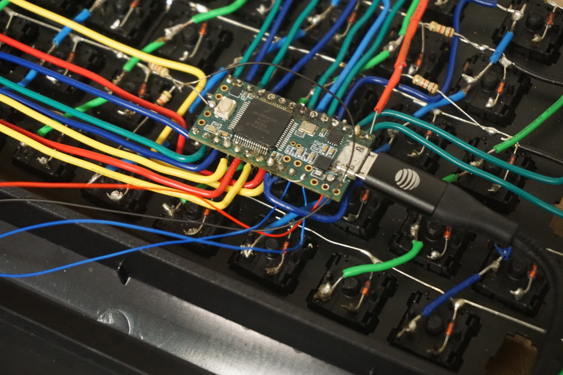
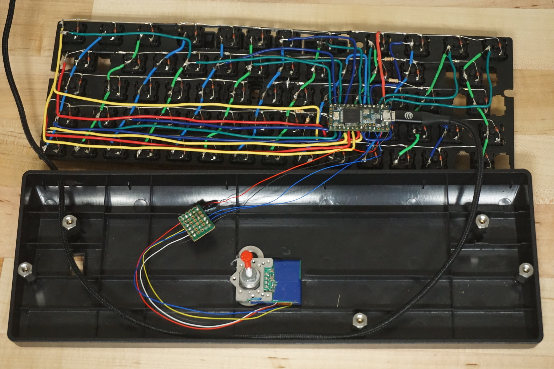
5. wire the microcontroller
With these newly soldered columns and rows it’s time to connect them to the microcontroller. First I connected the columns to the digital pins on the Teensy board, I had to resolder a lot of new wires onto the ends since I didn’t leave enough room or couldn’t bend it fully. I realized halfway through that you didn’t actually need to solder the connecting wire to the end of the columns like you need to with the rows, so I could have simplified it.
To connect the rows new wires are attached with different colors to make it easy to wire and trouble shoot.
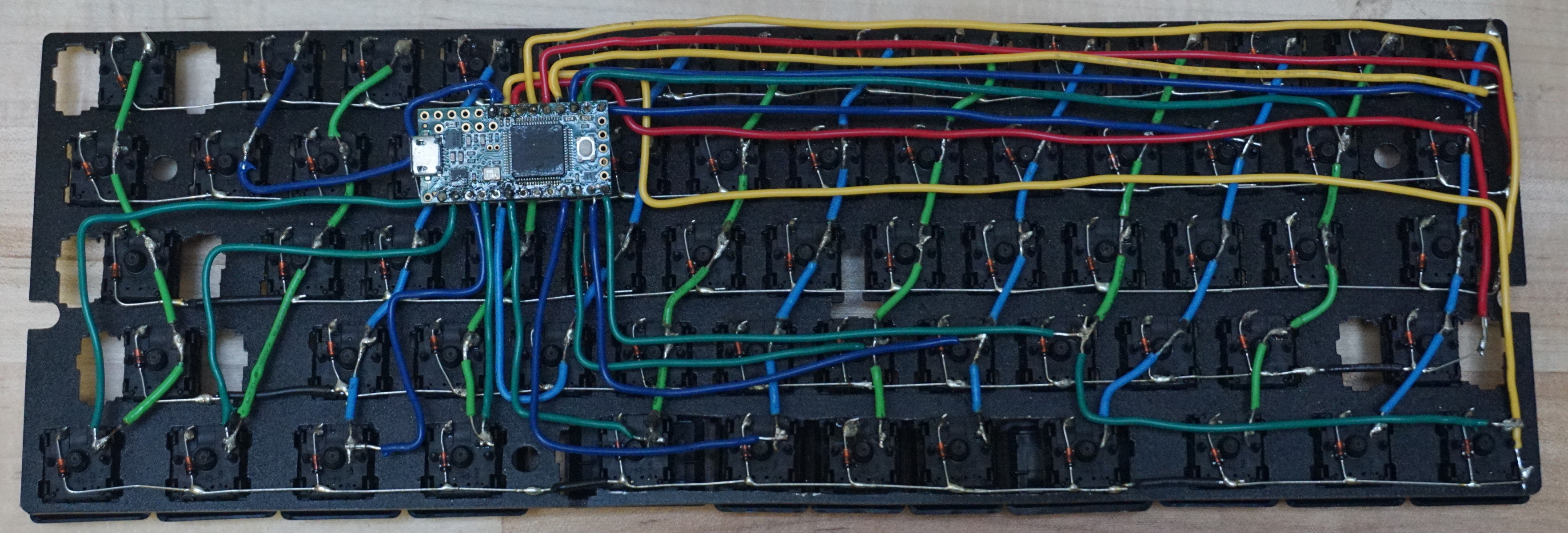
6. attach pull up resistors
Depending on the microcontroller you are using you might have to manually add pull up resistors to any of the input pins. Many microcontrollers do this for you, such as most Arduino boards. I found out the hard way that the Teensy 3.2 does not. These resistors have to be added to each of the input rows connecting them to ground, luckily because of the design of the matrix only 5 resistors are needed for the 5 corresponding inputs at each of the rows.
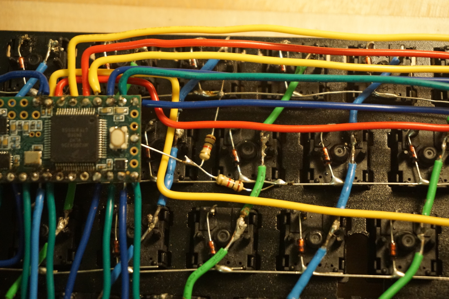
If I had know this about the Teensy before hand I would have probably come up with a better way then just adding the resistors free standing last minute.
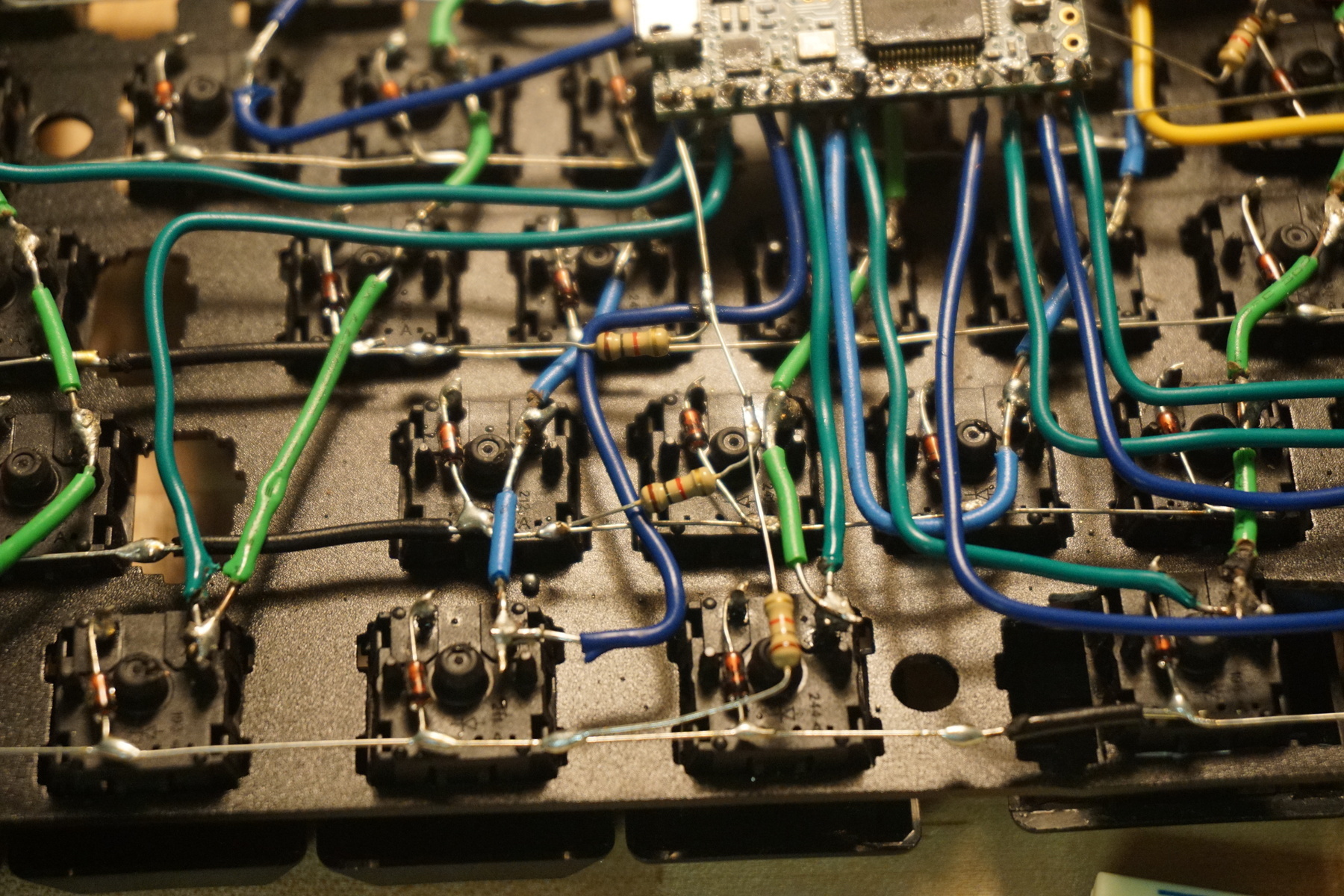
I used shrink wrap on the long portions of exposed wire to prevent any shorts when the keyboard is closed together.
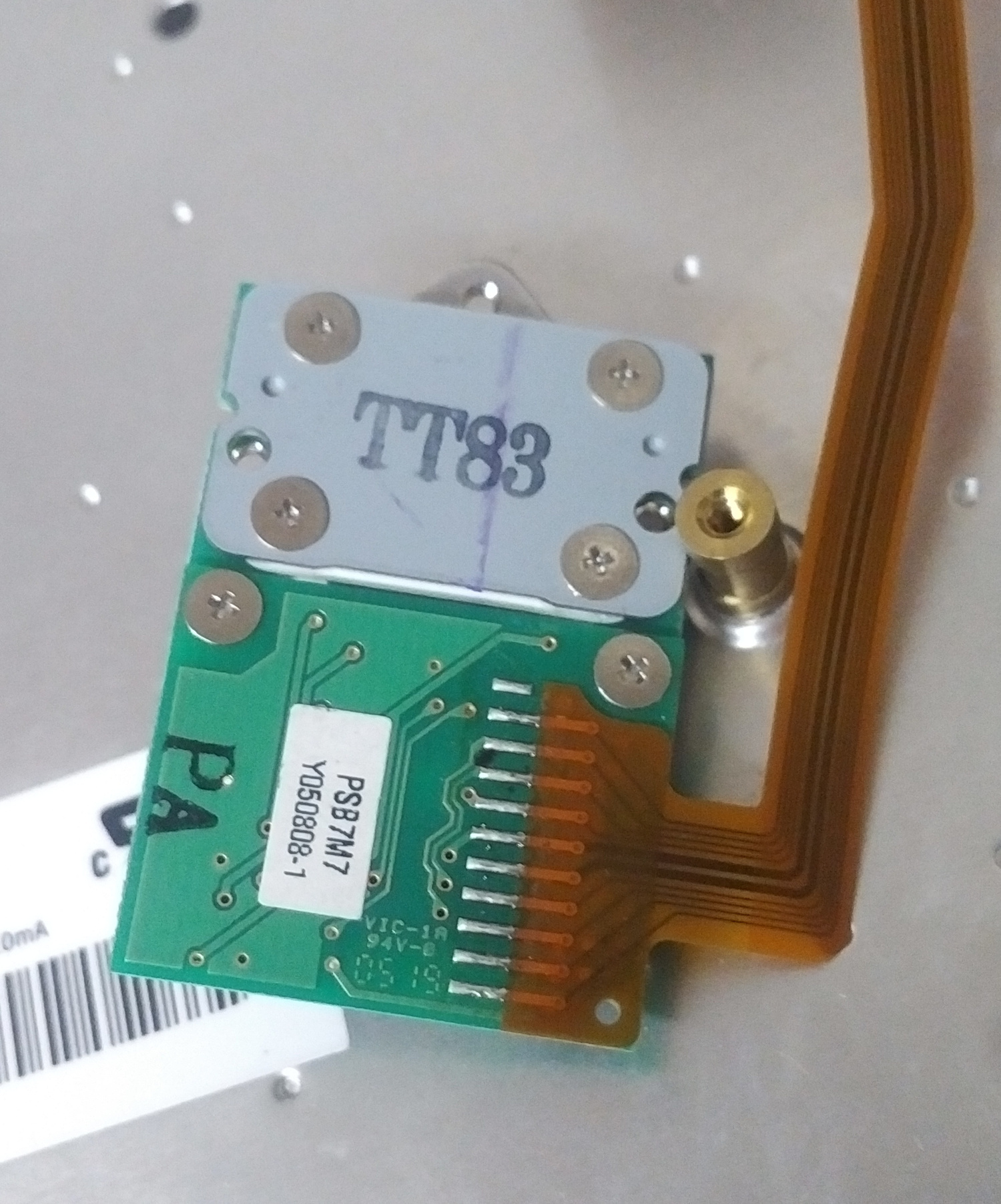
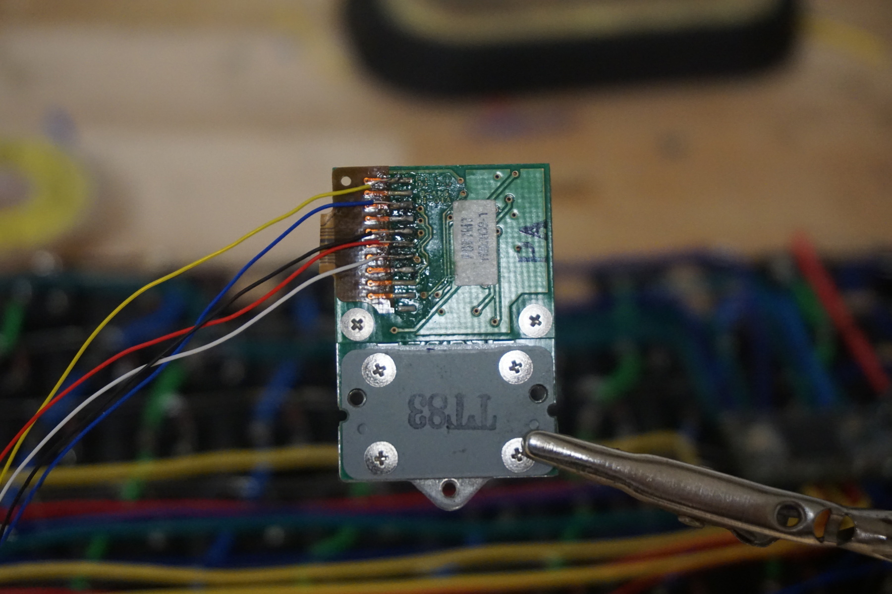
7. remove trackpoint
The easily way to build a trackpoint into our custom keyboard is to just savage an existing module from an old keyboard and wire it into ours. I found an old IBM ThinkPad replacement keyboard on eBay for cheap which will work perfectly well. There are tons of different keyboards with trackpoints that work, but the removal, wiring, and fitting might be slightly different.
To remove my trackpoint module form the ThinkPad keyboard I first took off the key caps around the red dot, exposing the screws attaching it. By unscrewing these the module should fall out.
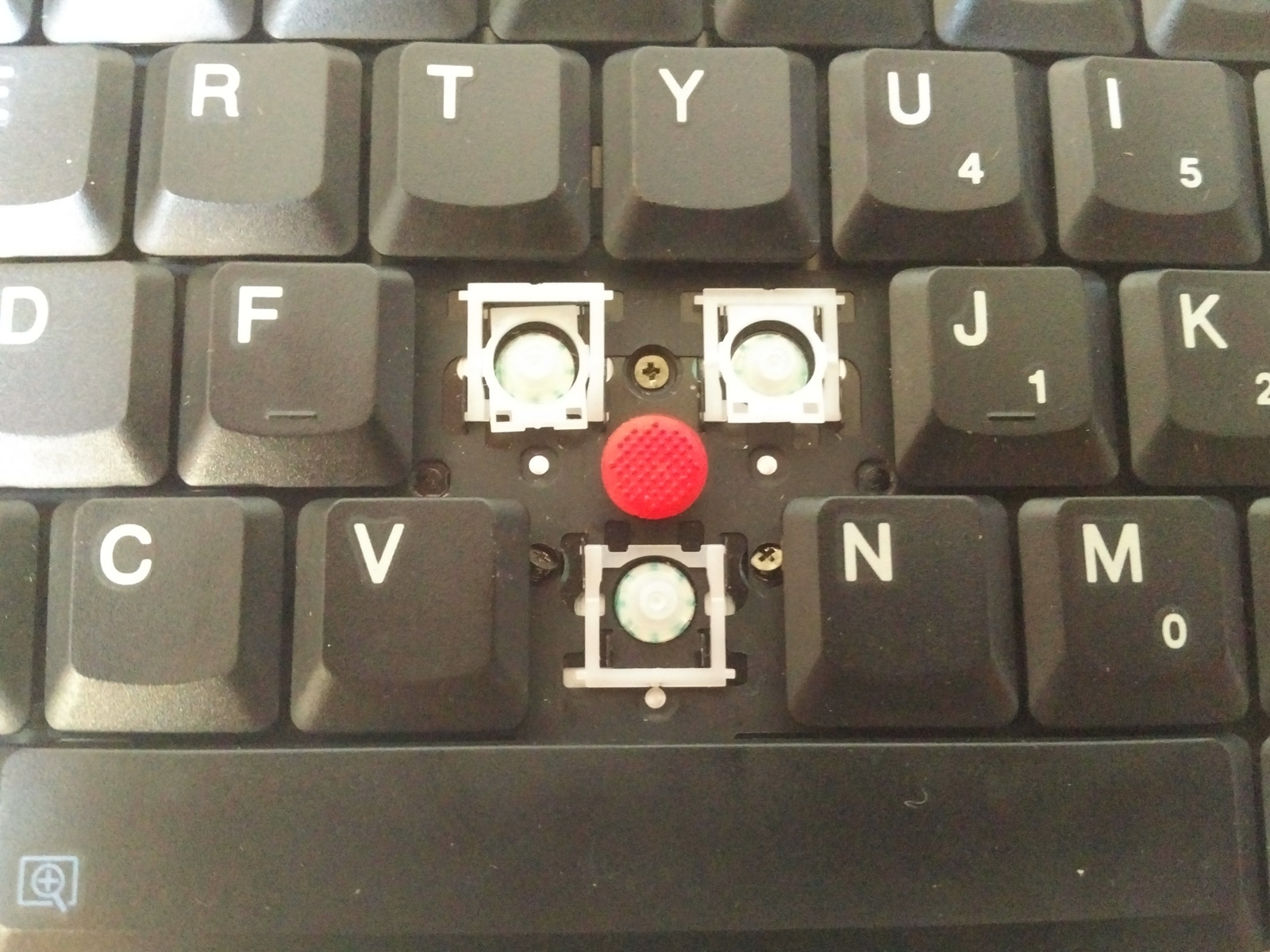
The ribbon cable connecting it can then be cut freeing the module. Cutting it at the base of the cable where it joins with the module’s board is fine since wires will be attached directly on to the exposed solder later.
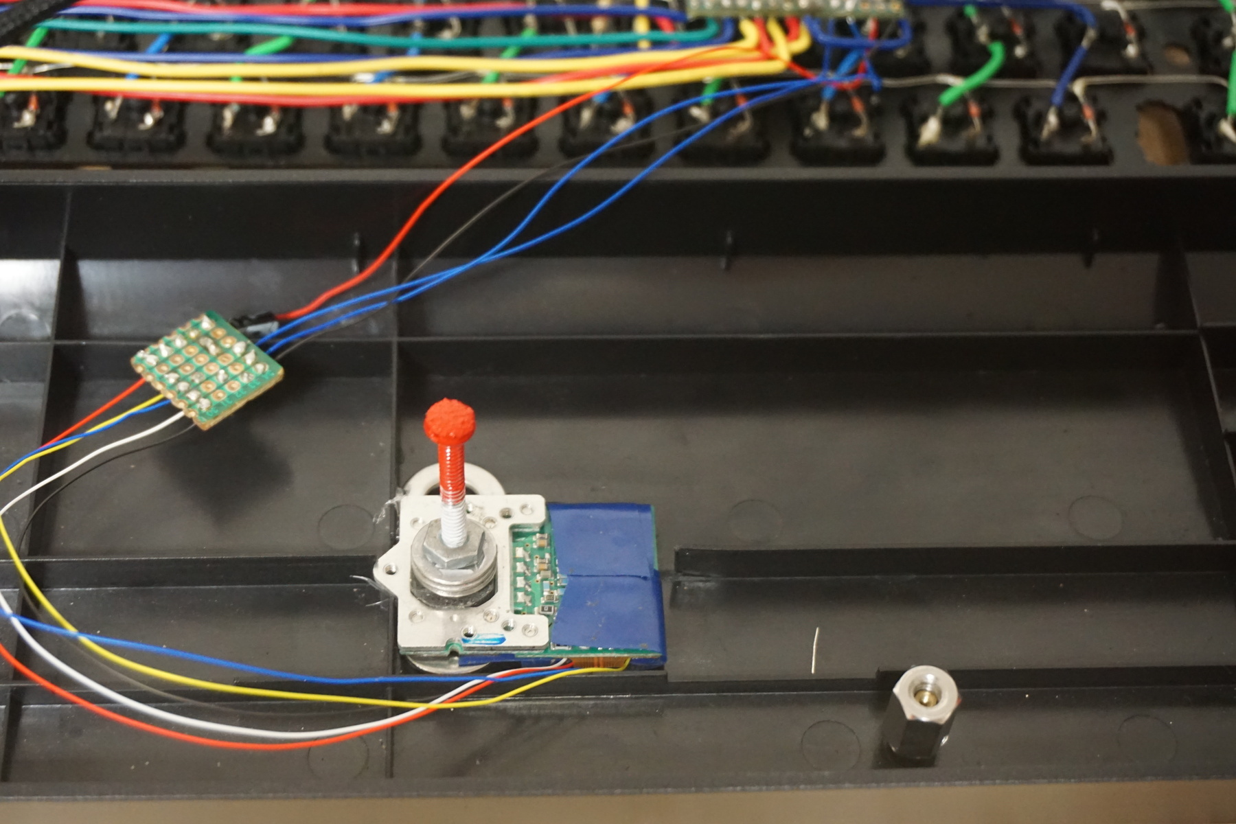
8. construct trackpoint circuit
This circuit will be used to connect the pins from the trackpoint module to the microcontroller
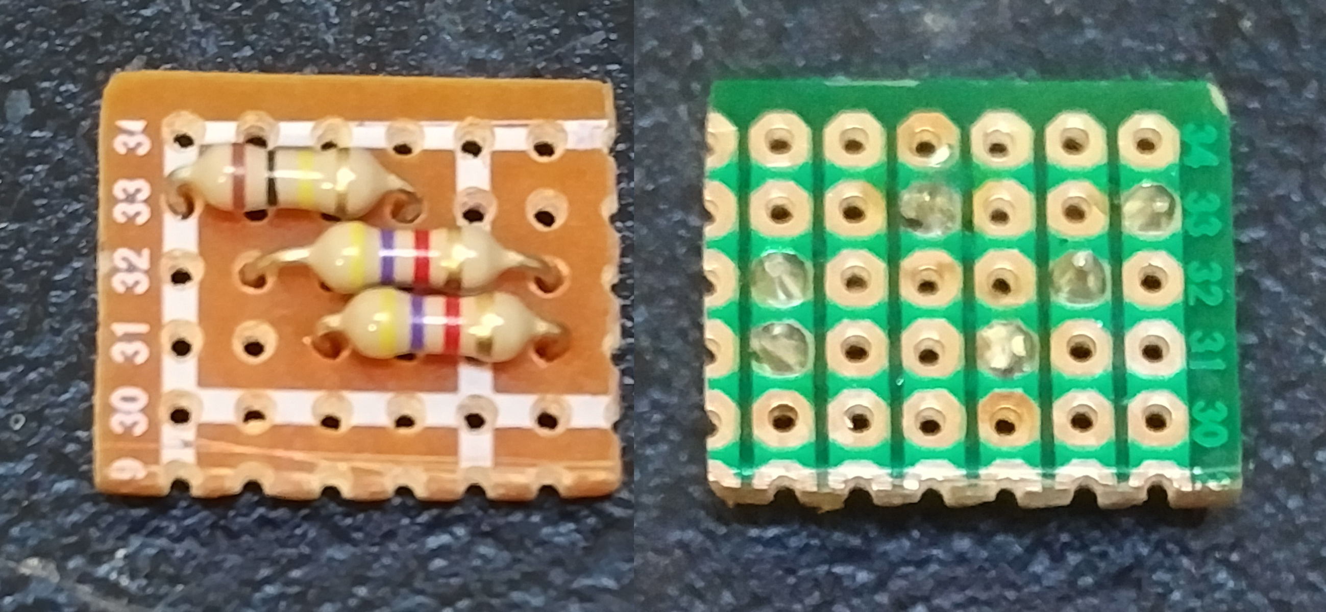
a) resistors
The bottom two resistors are pull-up resistors which connect the trackpoint’s clock and data lines to high so they are not left floating when there is no data passing through them. The top resistor is used with the next step to make an RC circuit which automatically triggers the reset pin after the appropriate amount of time has passed, instead of having to do it in code.
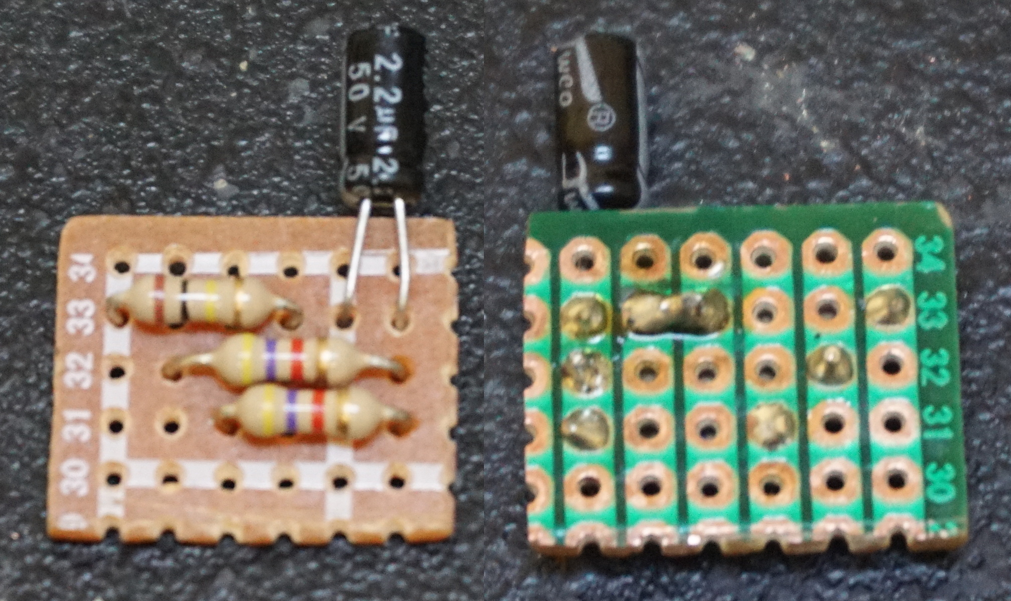
b) capacitor
Capacitor to complete the RC circuit in order to trigger the reset pin at the correct interval.
9. wire trackpoint
With the completed intermediating circuit you next need to solder the corresponding pins on the trackpoint module to the circuit. This GitHub repo has the pin out for various different modules so you can find the one you salvaged. Since the exposed pins on the module are normally very close together it is necessary to use the very thin 30 AWG wire here. I also recommend using some electrical type to make sure none of the wires come loose.
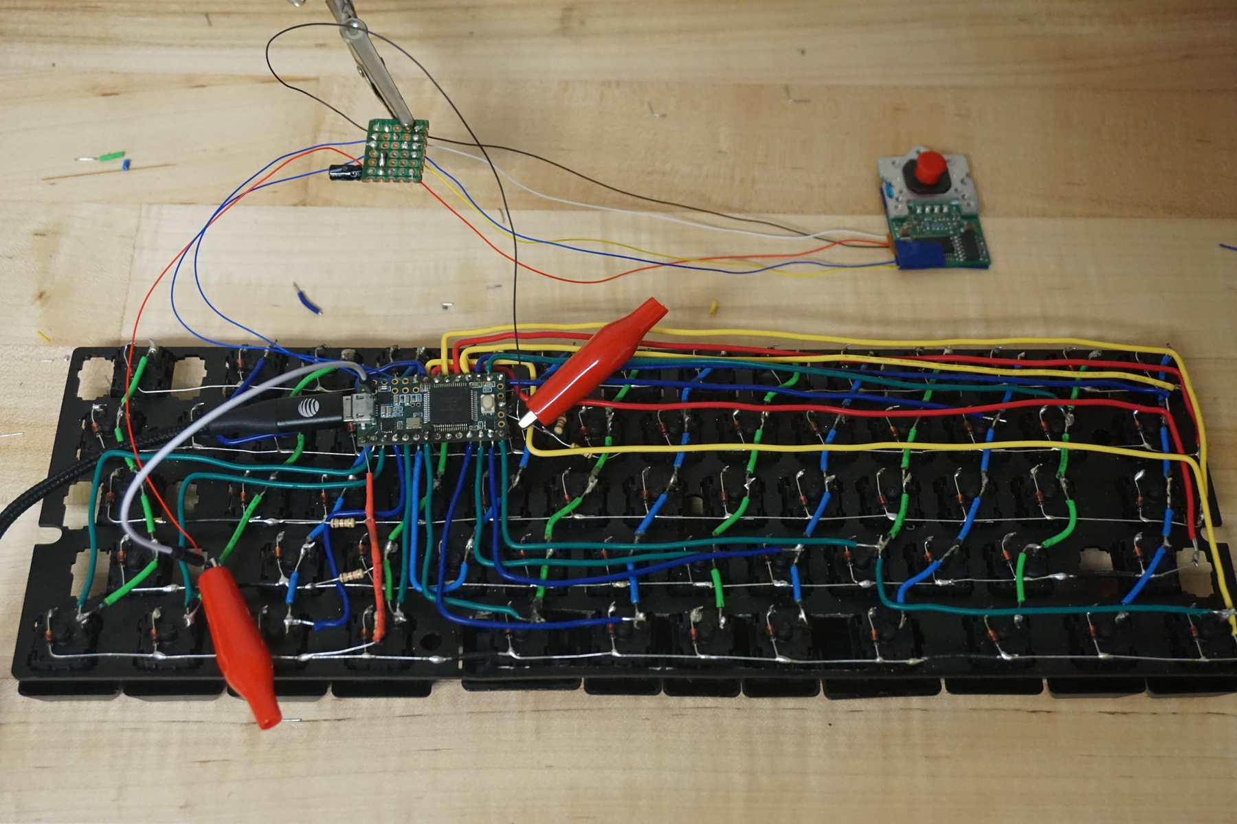
10. test trackpoint
In order to test to make sure the trackpoint works correctly solder more wire (any will do) to the other side of the RC circuit and use a breadboard or alligator clips to test the trackpoint, circuit, and wiring with the teensy.
11. flash firmware
To confirm that the keyboard is working correctly so far we need to connect the teensy to a computer and upload firmware to read all the inputs and communicate with your device. There are many different tutorials online about uploading code to our microcontroller, I used the official teensy arduino tutorial so that I could push code with the easy-to-use arduino IDE.
Once you know how to upload code we now need the actual code that’s going to make the keyboard work. Depending on the choice of microcontroller, the well supported QMK firmware is a good choice. Unfortunately I realized too late that the teensy 3.2’s new ARM processor was not supported when I originally tried QMK, so I had to write my own arduino code from scratch which can be found here. Either way since this is a custom hand wired board you will need to tweak the program to the layout you wired

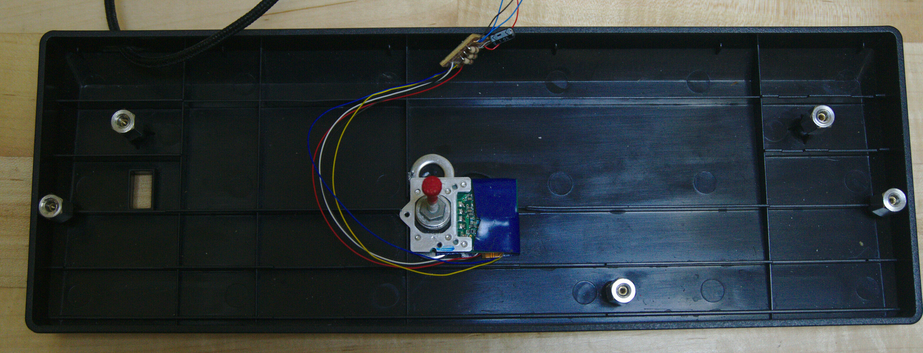
12. attach trackpoint
Once the teensy is working with the trackpoint it can be soldered permanently to the board.
The trackpoint module was then hot glued to the bottom of the case. Depending on the case the thin protruding support structures might need to be clipped off in order to fit the module as low as possible.
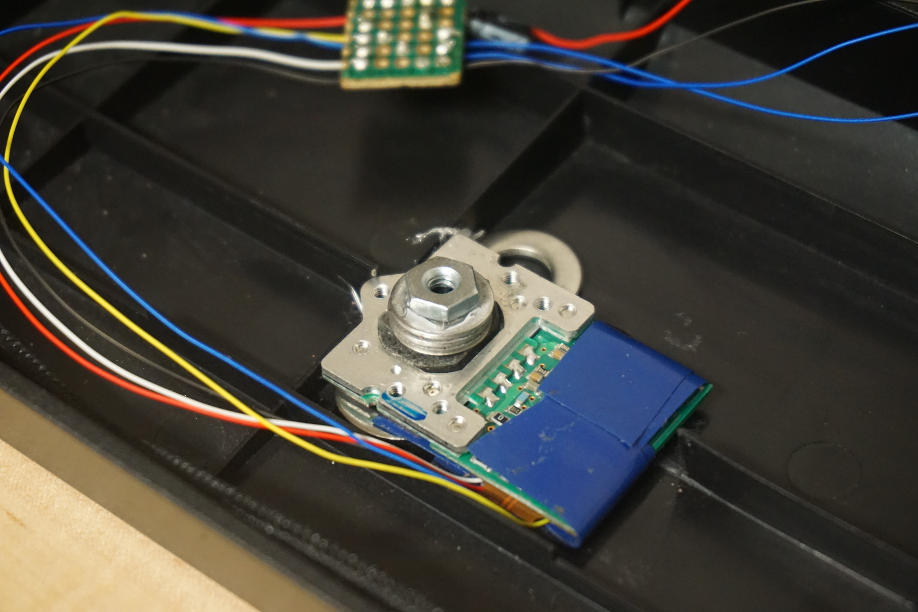
I chose to position the module sideways since placing it straight down would require me to cut out much more of the case’s supporting structure. This just meant that I needed to tweak the code a bit so that the new orientation is taken into account.
13. construct trackpoint stem
To control the trackpoint from outside the keyboard enclosure a stem needs to be attach to the top of the module. This is the point where you have to get pretty creative as there are many different ways to achieve this. Some people use a lip piercing, one of the keys themselves, or a simple screw. Since I had some screws and bolts laying around I opted for this option as it seemed the simplest.
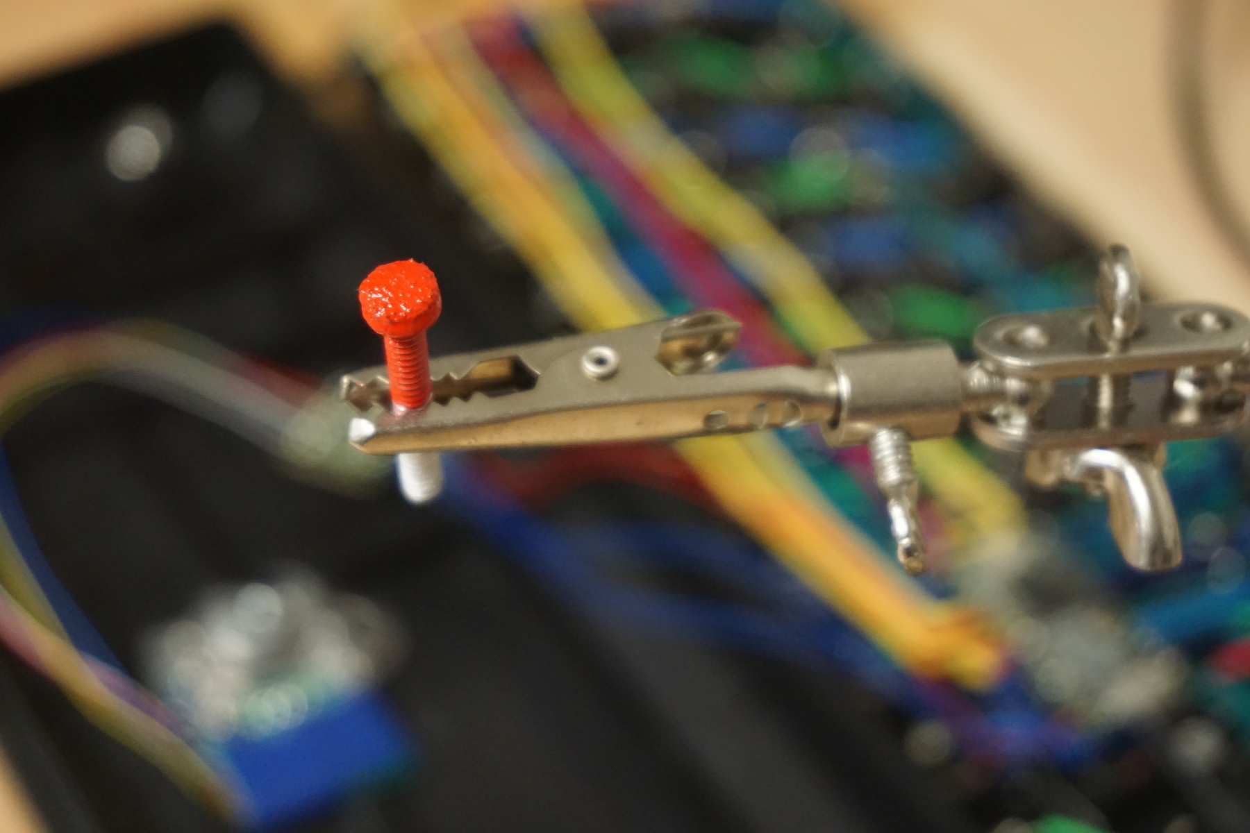
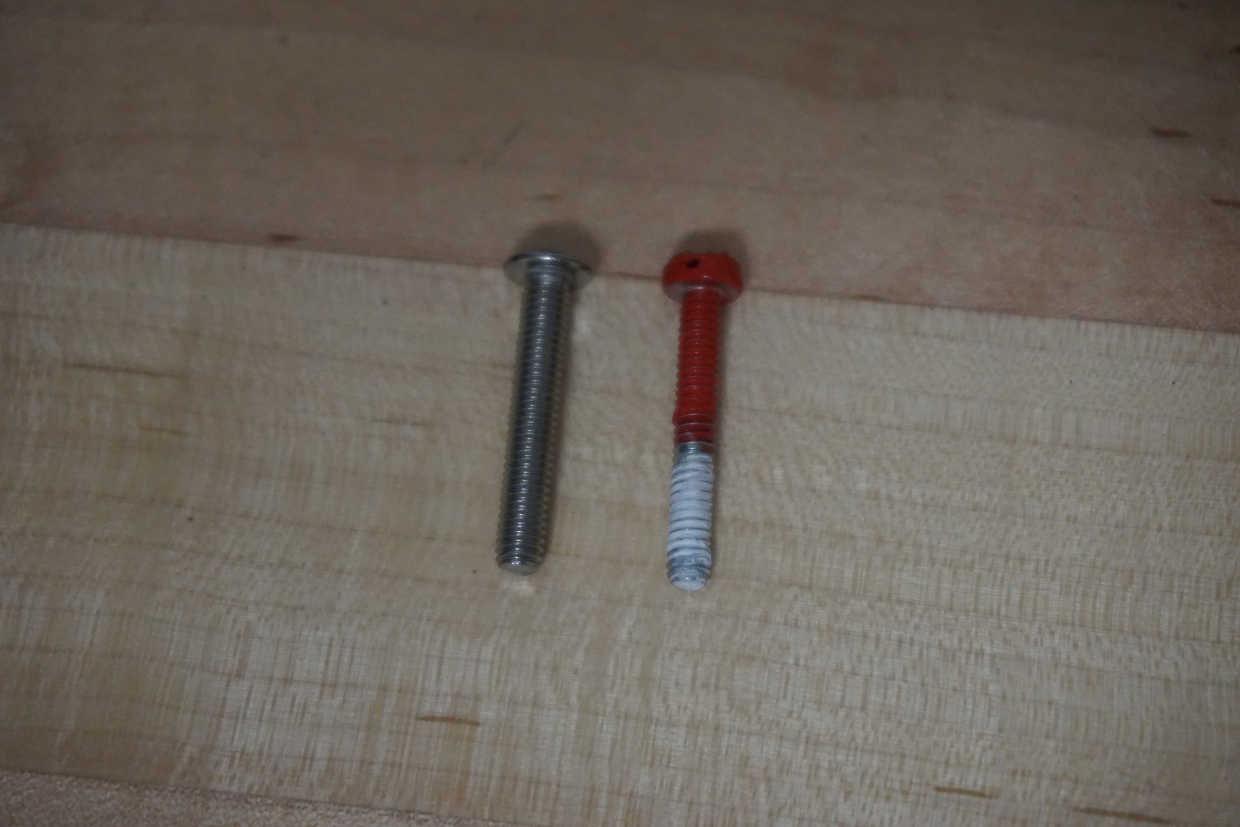
To make the screw feel more like a traditional trackpoint some coarse sandpaper cut with a hole puncher was glued to the top of the screw and red spray paint was coated on the top of it. While the sandpaper gives the screw texture, the paint covering it gives it a softer and rubbery feel which is much less harsh then the sandpaper by itself.
14. attach trackpoint stem
To attach the screw to the trackpoint the textured red control was removed and a series of washers and a bolt were first super glued together and then glued onto the controller of the module. This allows a short screw to be easily attach and detached from the board controlling the direction the cursor moves.
A small amount of silicone tape is added to the end of the threads of the screw to reduce the amount of play in the screw, making its movements more precise.
A new wire has to be connected as well to make the stem fit through the previously cut opening.
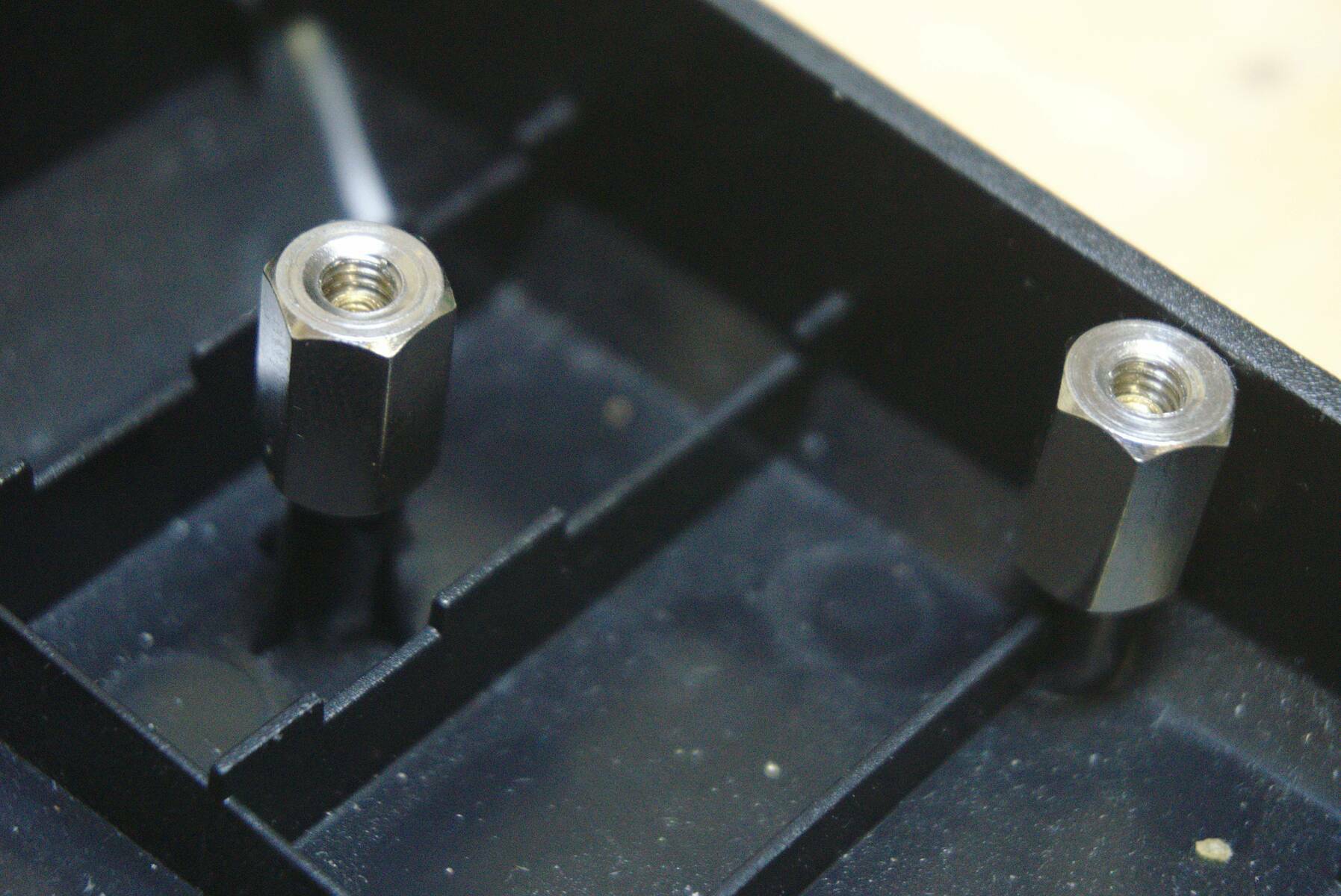
15. attach standoffs
Since the trackpoint requires extra room in the case the top plate needs to be raised above from where it normally sits so the keys aren’t interfering with the trackpoint. This can be done in many different ways, but I decided to go with motherboard standoffs that fit over the existing screw bases.
16. keycaps
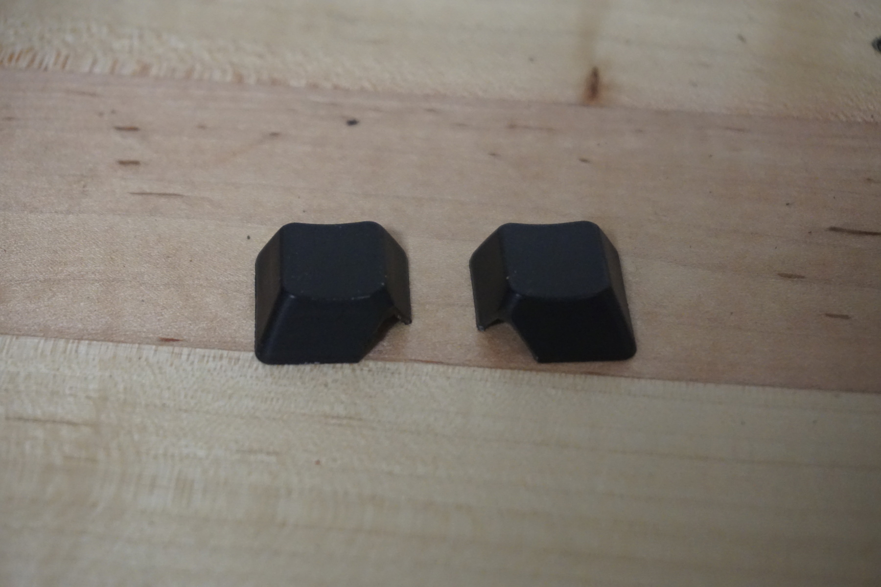
a) trim keycaps
To make room for the trackpoint stem outside of the cause and allow it to freely move the edges might have to be trimmed out of the surrounding keycaps. I did this by simply pressing hard on the corner with a sharp blade, but similar results could be achieved with a dremel, drill, or file. For me only the G and H keys needed to be modified, but depending on the trackpoint’s position the top of the B key might also need to be filed down.
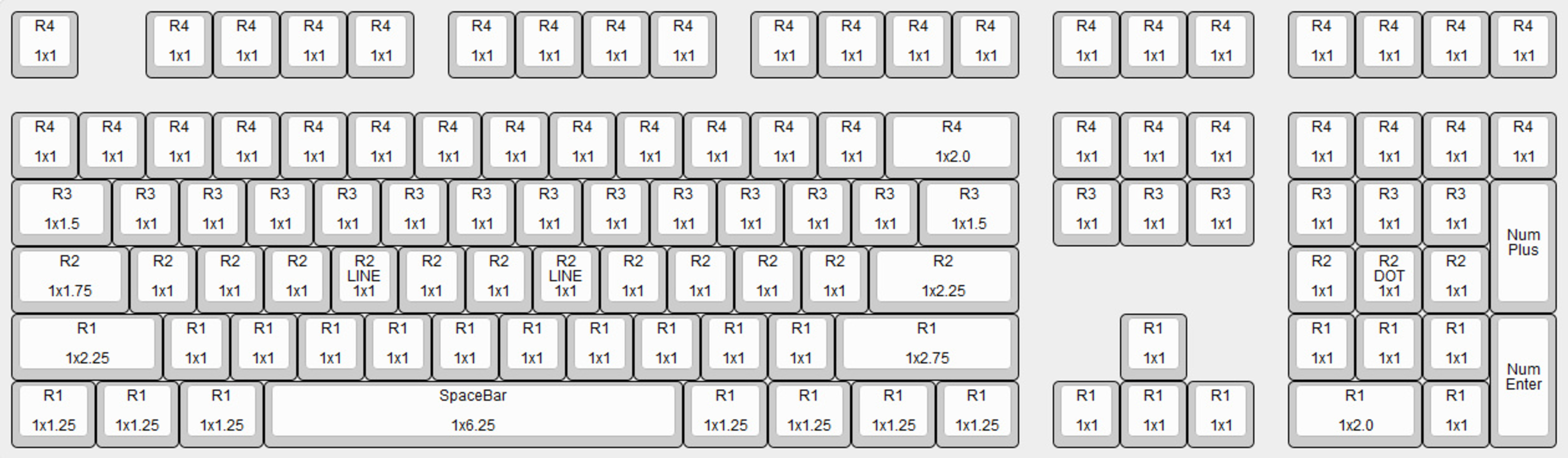
b) place keycaps
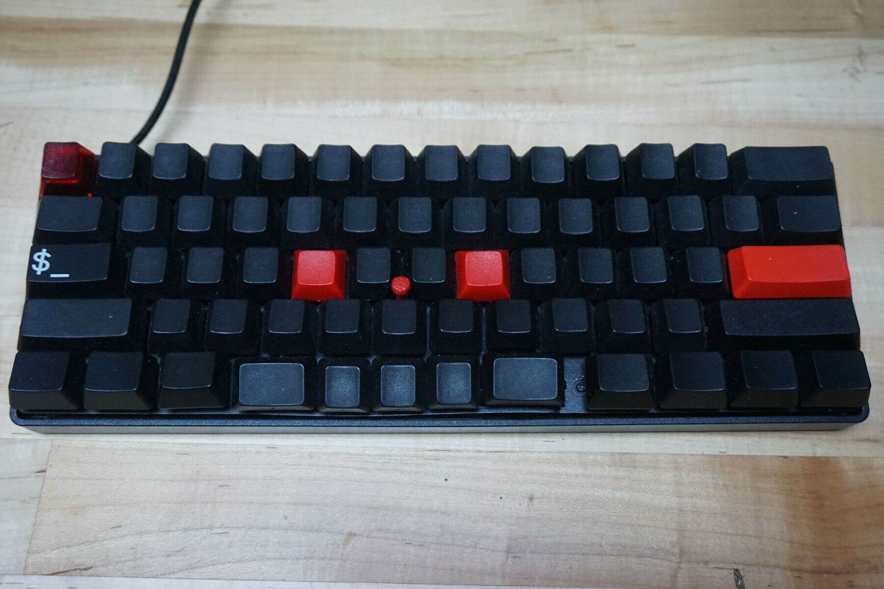
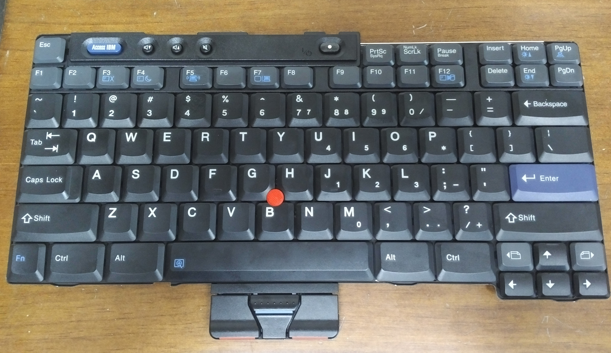
The rest of the keycaps can now be placed according to the layout below.
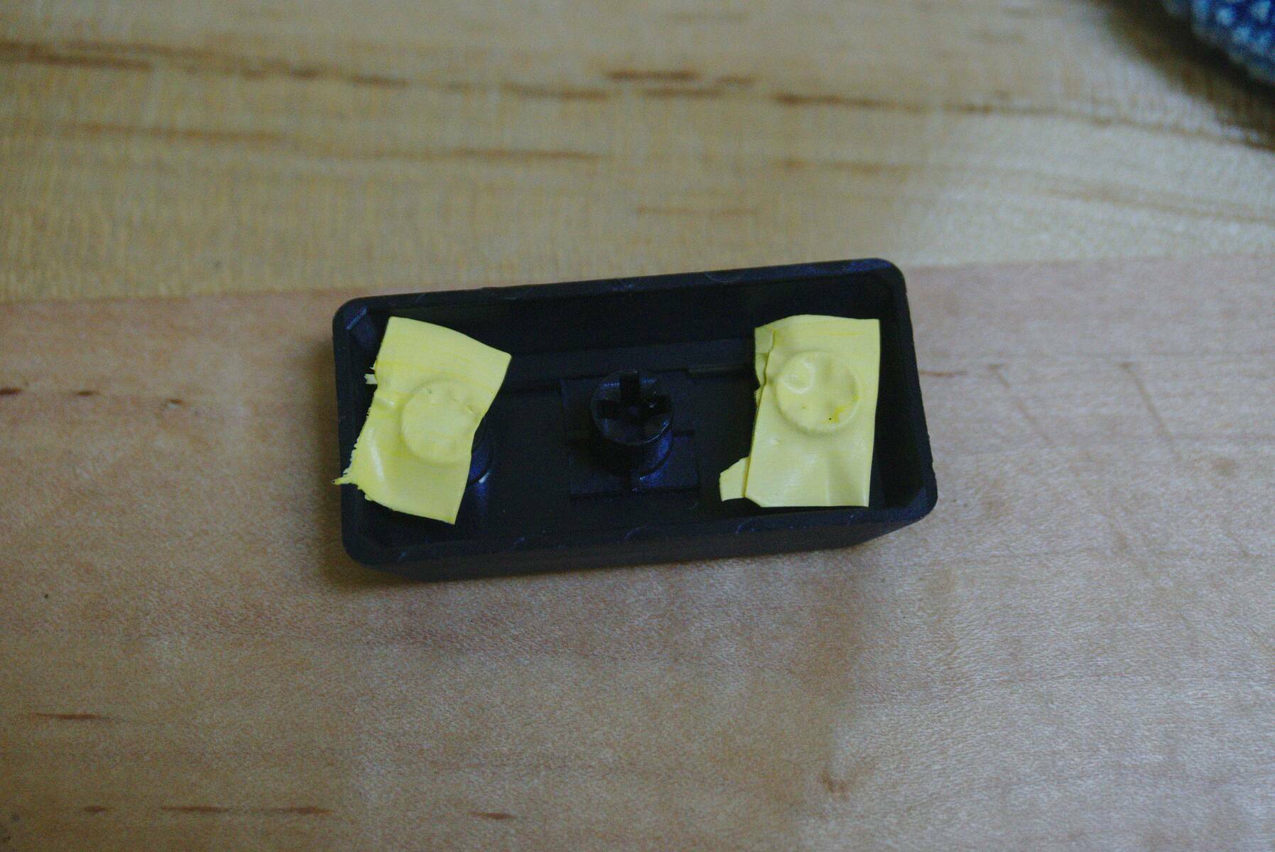
More silicone type might be required to get the keycaps with stabilizers to fit correctly.
future

In future projects I probably won’t choose to use a teensy 3.0 again unless there is significant shift away from the currently popular 2.3 non-ARM architecture supported by most firmwares.
I also need a micro USB port to attach to the case so the cable can be removed and reattached from outside, currently there is just a hole leading to the microcontroller directly.
If I were doing it over I would also think more careful about where I position the microcontroller and wires since right now the USB port on the board is facing away from the case’s opening making the cable be a little tangled inside.
Overall I am extremely happy with how the keyboard turned out and learned a lot from making it myself. Feel free to contact me with any questions or advice with your own keyboard!
see also
Here are some other useful guides which I used: